

Triodes and the Control Grid
Series: Structure and Operating Principles of Vacuum Tubes

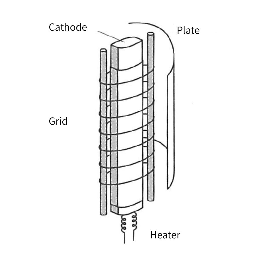
In an operating diode, electrons flow from the cathode (or filament) toward the plate. The current between the cathode and plate increases according to the 3/2-power law of the plate voltage. Here, let us consider a vacuum tube in which a metal lattice or wire-mesh structure is inserted between the cathode and plate, as shown in Fig. 2-19.
When a negative voltage of several volts is applied to this lattice or mesh electrode—the grid—the current clearly decreases compared with the diode state, as shown in the relationships in Figs. 2-20a and 2-20b. This is because the negative charge of the electrons and the negative charge of the grid repel each other through Coulomb force, so only some of the electrons emitted from the cathode can reach the plate.
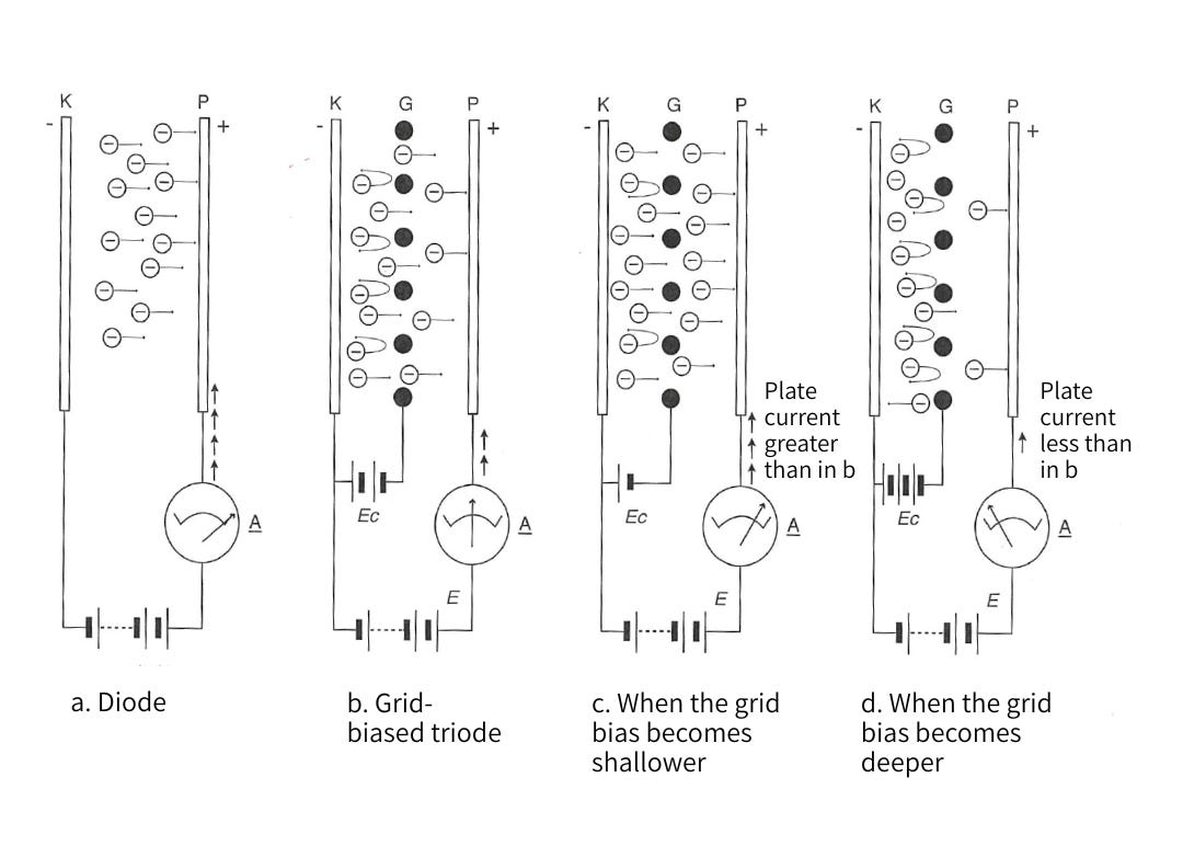
Using Fig. 2-20b as the basic operating state, let us now shift the grid voltage in the positive direction, as shown in Fig. 2-20c. The electrons near the cathode then experience less repulsion from the grid, more electrons reach the plate, and the current increases. Conversely, if the negative voltage on the grid is made deeper, as shown in Fig. 2-20d, the repulsive force of the grid increases, and fewer electrons reach the plate. During this process, the grid always remains at a negative potential, so no current flows into it; the required change is only a voltage change. In other words, we can see that increasing or decreasing the grid voltage changes the electron flow from the cathode to the plate.
A vacuum tube that uses this action for amplification and other purposes is called a triode. The grid inserted between the cathode and plate to control the current is called the control grid.
The negative voltage applied to the grid as an operating prerequisite is called the grid bias. If no bias is applied and a grid voltage of 0 V is used as the operating reference point, then as soon as the incoming signal voltage—normally an AC voltage centered on 0 V—enters the positive region, the control grid begins to collect electrons from the cathode, causing grid current to flow. In other words, during the positive half-cycle of the AC signal, controlling the plate current requires not only voltage but also current. Except in special cases, this is undesirable.
Grid bias can be obtained either by preparing a separate negative power supply and steadily applying a negative voltage of several volts to several tens of volts, or by applying a corresponding positive voltage to the cathode, thereby making the control grid relatively negative. In ordinary voltage-amplifier circuits, a sufficiently negative grid-bias voltage is applied so that even when the grid voltage rises due to the incoming signal voltage, it always remains within the negative region.
The control grid is typically constructed by winding a fine wire in a lattice form around two cylindrical support rods placed between the cathode and the plate. Other types include grids made from wire mesh, and frame grids, in which a strong molybdenum frame is made and wire thinner than a human hair is wound onto it under high tension, achieving both mechanical strength and high transconductance, which will be discussed later.
The abbreviation “G” is used, from the word “Grid.”